Scanning Optical Systems
Technology Overview
This technology scans an area irradiated with light. As laser light becomes more diverse and more sophisticated, its applications are expanding, and through scanning, it is possible to increase the dimension of space by irradiating light from points to lines to surfaces to 3-dimensional objects. When irradiating light onto an object and obtaining information about the object from its response, such as in a measurement system, it is possible to obtain information on the irradiated area separately from information on other areas, thereby increasing the spatial resolution of the information. Furthermore, when using a scanning optical system for processing using light, by changing the irradiated area and scanning according to the power of the light and the shape of the target object, it is ultimately possible to process the desired shape.
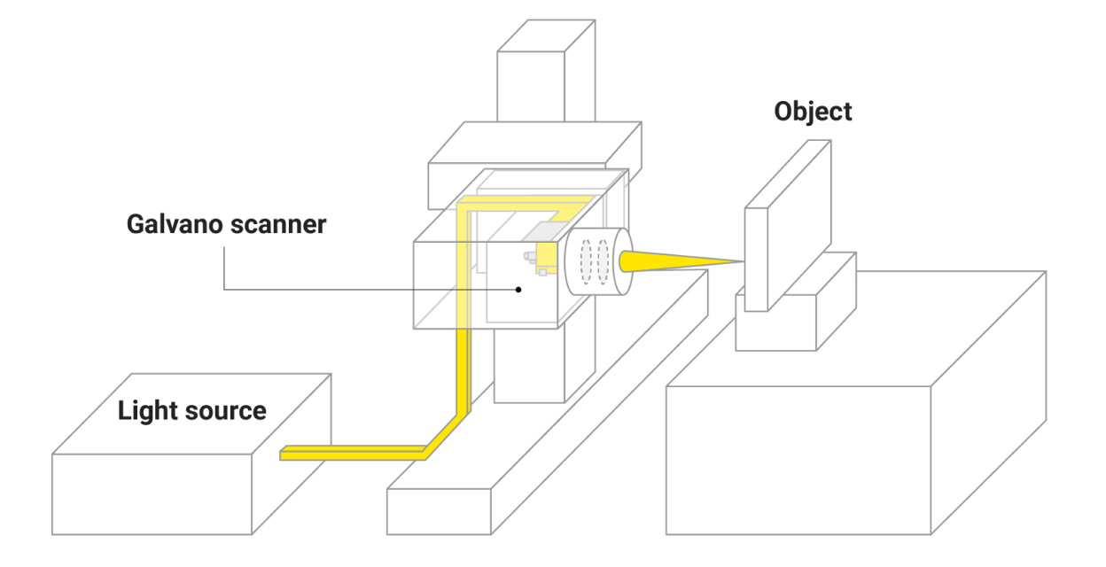
Generally, laser light is irradiated onto a mirror, and by changing the mirror's angle, the light can be scanned. In practice, laser light gradually spreads out, so when high spatial resolution is required in measurement or processing, the light is first collimated and then focused onto the target using a lens. In scanning, by changing the direction of the collimated light entering this lens using a mirror, the focal point can be moved on the target object. In addition to scanning by mechanically driving a single mirror, there is also scanning by mechanically driving a digital mirror device (DMD) and scanning with elements that utilize electro-optic and acousto-optic effects. The appropriate method is selected depending on factors such as scanning range, speed, and control.
At Nikon, this is used for inspections and measurements that obtain information about an object by irradiating it with light and detecting reflected and scattered light, as well as for processing objects using the energy of the irradiated light.
For example, in a confocal fluorescence microscope, fluorescence is detected by irradiating each point of the object being observed. When observing finer cell structures, it is preferable to be able to focus light, and accurately capturing cell movements necessitates having no time lag between observation points, so high-speed scanning is required.
In this way, it is necessary to have an optical system that can cope with the effects of heat and vibration while also accommodating the required specifications such as light source conditions, scanning range, resolution, and equipment size.
Technology Application Examples
Fundus Cameras
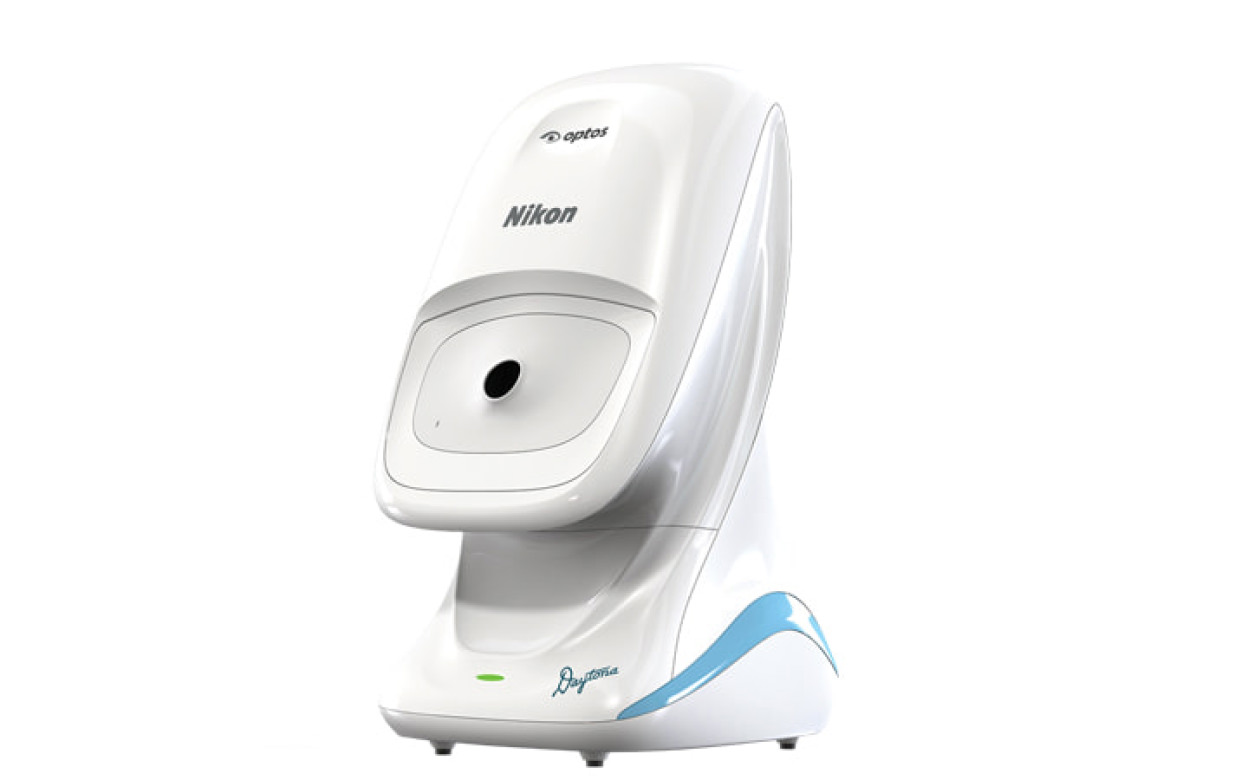
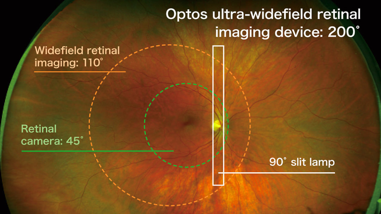
The ultra-wide angle scanning laser ophthalmoscope manufactured by Optos, a Nikon Group company, is a fundus imaging device that can acquire digital images of approximately 80% of the retina (with a 200°field of view) in just 0.4 seconds and aids in the detection of many diseases diagnosable through retinal images. It is used not only for detecting eye problems such as retinal detachment but also for diagnosing systemic diseases like diabetes due to diabetic retinopathy, making it effectively utilized in ophthalmology medical facilities. It provides various benefits for patients, such as eliminating the need for eye drops to dilate the pupils, which is required with general fundus imaging devices, allowing patients to return to their daily activities immediately after the examination and significantly shortening the examination time.
The key feature of Optos’ ultra-wide angle scanning laser ophthalmoscope is its unique scanning optical system, which combines an elliptical mirror with a concave three-dimensional shape and a laser that scans the retina. The laser is reflected off an elliptical mirror and scans the retina through the patient’s pupil. Laser light is irradiated while changing the angle of incidence using a galvanometer mirror, which can perform high-speed scanning by reciprocating motion, allowing for the acquisition of high-definition images with an extremely wide angle of view at high speed.
Technologies related to these examples
Related Technology
Optical Modulation
Light exhibits wave properties and can be manipulated freely by changing the amplitude, phase, and polarization of the wave. For example, a desired light intensity distribution can be achieved by spatially modulating the phase and interfering with other light, or to adjust the light intensity using an optical element that only allows passage of vibration in a specific direction.
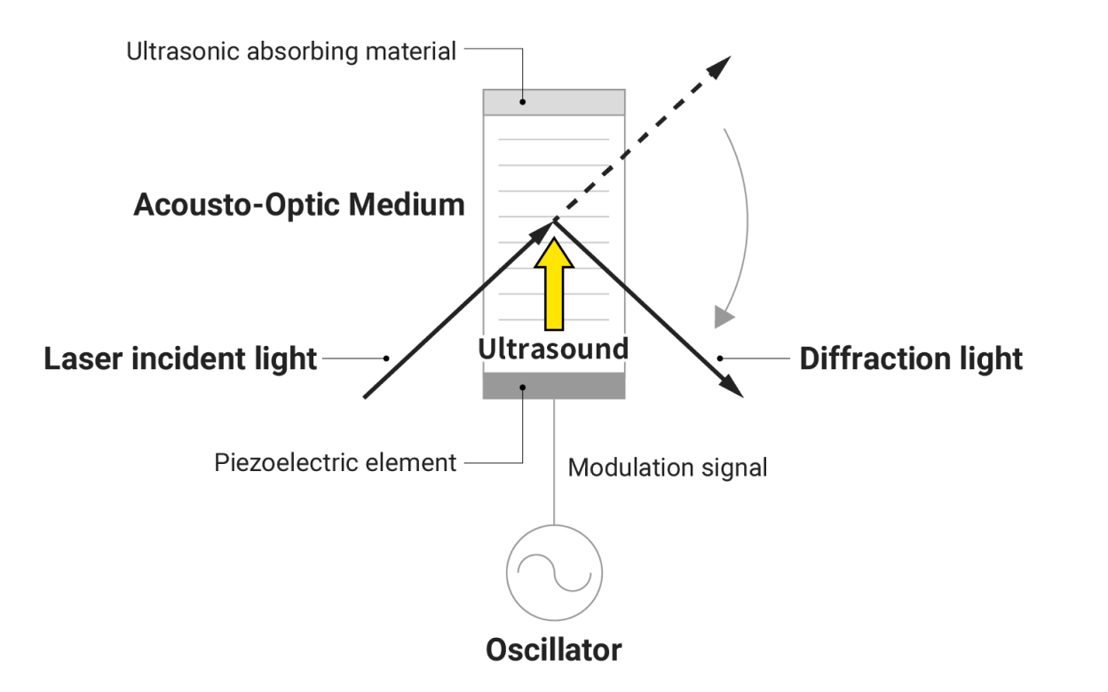
In the communications field, optical modulation is used to transmit information by putting information on the modulated part, but Nikon’s products use optical modulation to obtain the desired light properties. There are various ways to modulate light depending on the characteristics of the light one wants to change. For example, in an acousto-optic modulator, ultrasonic waves are applied to a specific crystal material to generate a regular refractive index distribution and diffract light. By changing the frequency of the ultrasonic waves, the regularity of the refractive index distribution can be adjusted to control diffraction.
At Nikon, deflection, which involves changing the direction of light, is often necessary among optical modulations. For example, in scanning biological microscopes, it is essential to scan the entire sample with light, allowing for rapid observation of morphological changes in cells without time lag. In optical processing and laser radar used for industrial purposes, both speed and accuracy are required.
In optical modulations other than deflection, the phase distribution of light is modulated within the illumination optical system of semiconductor lithography equipment to achieve the desired illuminance distribution.
Main Related Products
You can search for articles related to Nikon’s technology, research and development by tag.

